Get to know the board
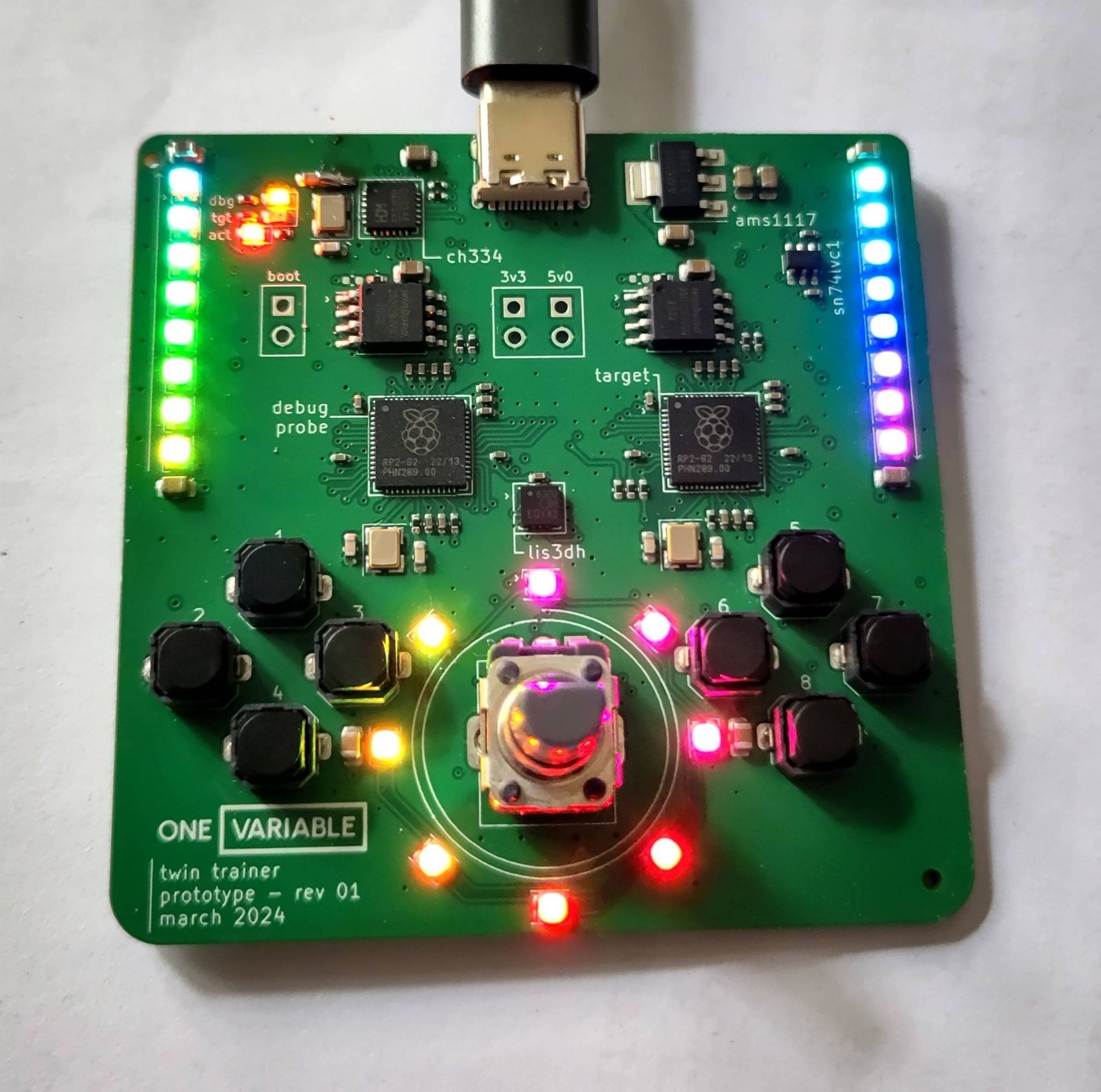
This is our board, the OneVariable Twin Trainer.
Links
You can view the KiCAD design files in the hardware repo.
You can view the schematic as a PDF here.
Block Diagram
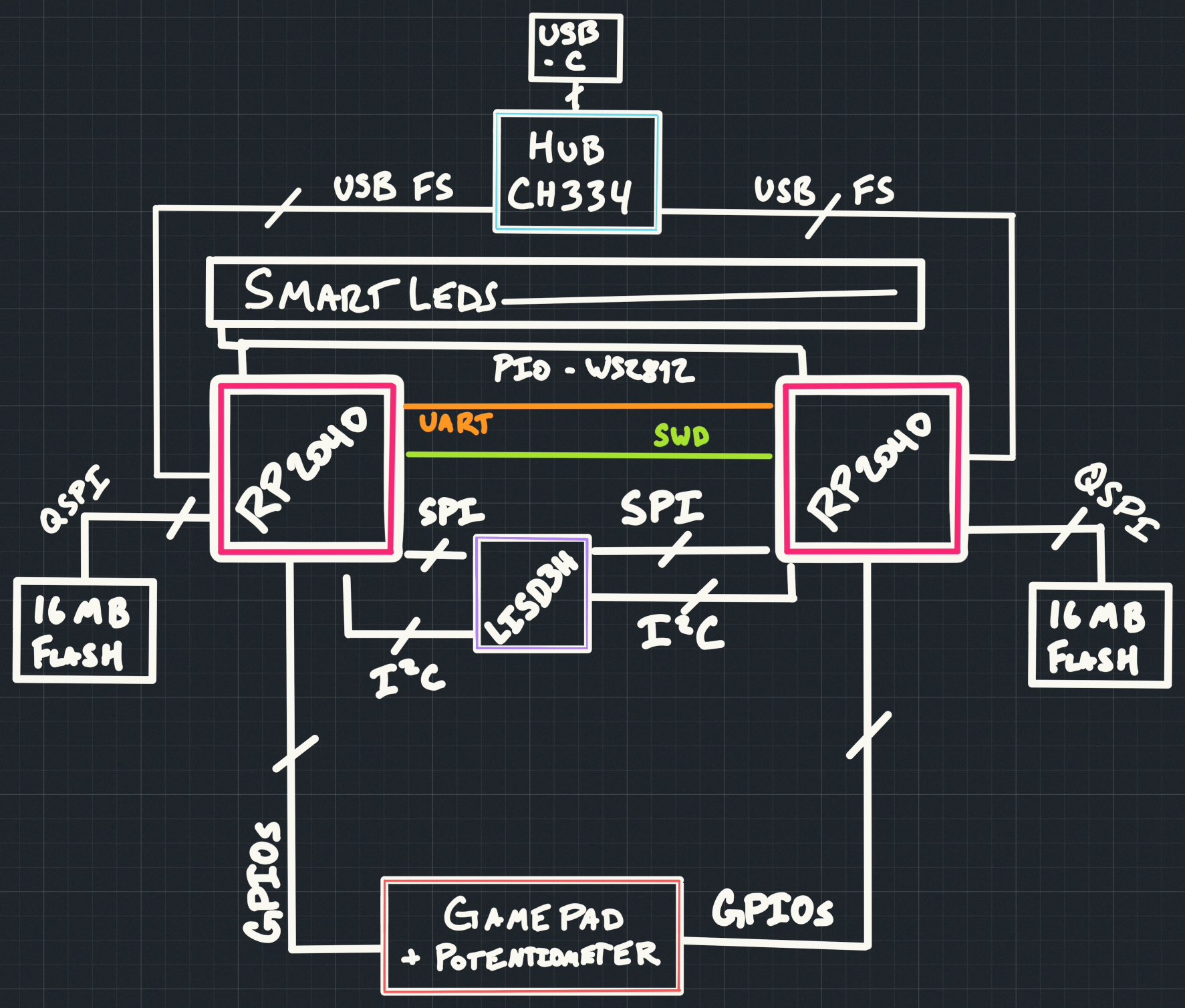
Main Parts
| Part Usage | Part Number | Notes |
|---|---|---|
| Debugger | RP2040 | Using debugprobe firmware |
| Target | RP2040 | Dual Core Cortex-M0+ at 133MHz 264KiB RAM 16MiB QSPI Flash |
| USB Hub | CH334F | Allows both chips to talk through one USB port |
| Accelerometer | LIS3DH | Usable over SPI or I2C, we will use SPI |
| SmartLEDs | TX1812Z5 | Similar to WS2812B, SK6812, or "neopixels", 16M color |
| Buttons | K2-1817UQ | Square soft push buttons |
| Potentiometer | RK09D1130C3W | 10K Potentiometer, 0v0 to 3v0 |
GPIO List (target board)
| GPIO Name | Usage | Notes |
|---|---|---|
| GPIO00 | Button 1 | Button Pad (left) - active LOW |
| GPIO01 | Button 2 | Button Pad (left) - active LOW |
| GPIO02 | Button 3 | Button Pad (left) - active LOW |
| GPIO03 | Button 4 | Button Pad (left) - active LOW |
| GPIO04 | SPI MISO/CIPO | LIS3DH |
| GPIO05 | SPI CSn | LIS3DH |
| GPIO06 | SPI CLK | LIS3DH |
| GPIO07 | SPI MOSI/COPI | LIS3DH |
| GPIO08 | I2C SDA | LIS3DH (not used) |
| GPIO09 | I2C SCL | LIS3DH (not used) |
| GPIO10 | Interrupt 2 | LIS3DH (optional) - active LOW |
| GPIO11 | Interrupt 1 | LIS3DH (optional) - active LOW |
| GPIO12 | Not Used | |
| GPIO13 | Not Used | |
| GPIO14 | Not Used | |
| GPIO15 | Not Used | |
| GPIO16 | UART TX | Debugger UART |
| GPIO17 | UART RX | Debugger UART |
| GPIO18 | Button 5 | Button Pad (right) - active LOW |
| GPIO19 | Button 6 | Button Pad (right) - active LOW |
| GPIO20 | Button 7 | Button Pad (right) - active LOW |
| GPIO21 | Button 8 | Button Pad (right) - active LOW |
| GPIO22 | Not Used | |
| GPIO23 | Not Used | |
| GPIO24 | Not Used | |
| GPIO25 | Smart LED | 3v3 output |
| GPIO26 | ADC0 | Potentiometer |
| GPIO27 | Not Used | |
| GPIO28 | Not Used | |
| GPIO29 | Not Used |